
Buyers usually arrive at a wood pellet production line with one number in mind: tonnes per hour. That number matters, but it is the last thing to fix, not the first. A line that runs at its rated capacity every shift is built backwards from the pellet specification the market demands, then matched through chipping, grinding, drying, pelletizing and cooling so that no stage starves or buries the next one. Get the sequence wrong and the symptoms show up quickly — a dryer that cannot hold 10% moisture in humid weather, a pellet mill that blocks every time the sawdust gets coarse, fines above contract limits, and an energy bill nobody can explain.
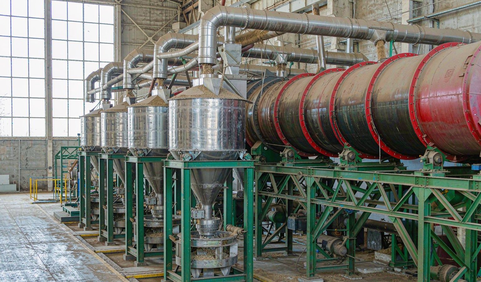
This guide walks through a wood pellet production line stage by stage, with published energy and mass-balance figures at each step, and ends with a configuration table you can compare against quotations. The equipment references come from our own standard range for biomass lines, so the numbers reflect what we actually build rather than a generic brochure.
Start From the Pellet Specification, Not From the Machine
Every downstream decision — screen sizes, drying temperature, die thickness, cooling time — exists to hit a measurable fuel specification. If you plan to sell into Europe, your reference point is the ENplus scheme, which is built on the ISO 17225-2 standard and adds supply-chain requirements of its own. The core production targets are worth printing and putting on the control room wall:
| Parameter | ENplus A1 requirement | What it demands from the line |
|---|---|---|
| Diameter | 6 mm or 8 mm | Die hole selection; 6 mm dominates residential markets |
| Length | 3.15–40 mm | Knife adjustment at the die face; keep over-length pieces under 1% |
| Moisture | ≤ 10% | Drying stage control; feed the mill at 10–15% and cool down from there |
| Ash | ≤ 0.7% | Raw material discipline: debarking, no sand, no bark in A1 feedstock |
| Mechanical durability | ≥ 98.0% | Correct die compression ratio, conditioning temperature, cooling |
| Bulk density | 600–750 kg/m³ | Fiber preparation and die L/D; low density usually means a short die |
Two of these deserve emphasis because they are where new plants lose money. Ash at 0.7% is unforgiving: sand introduced during log handling or bark content can push you past it, and no machine downstream can remove minerals. Durability at 98% is a process property, not a machine property — it comes from particle size distribution, conditioning, and the die’s compression ratio working together. The ENplus certification scheme publishes the full handbook with sampling and testing rules, and it is worth reading before you commit to a plant layout, because storage and load-out practices are audited too.
The Seven Stages and Where Capacity Is Lost
A complete line for log-grade raw material runs through seven stages:
1. Receiving and debarking → 2. Chipping → 3. Primary grinding → 4. Drying → 5. Fine grinding → 6. Conditioning and pelletizing → 7. Cooling, screening and bagging.
If your feedstock is already dry sawdust from a sawmill or furniture plant, stages 1, 2 and 4 shrink or disappear — which is why two plants with the same pellet mill can have completely different footprints and budgets. The reverse is also true: a plant designed around wet chips will be oversized for a dry-sawdust client, and the buyer who pays for drying capacity they never use has wasted capital.
Capacity is lost at the joints between stages more often than inside any single machine. A pellet mill rated for 3 t/h that receives sawdust at 18% moisture will not run at 3 t/h; a dryer fed by one hammer mill running at half its screen capacity will cycle on and off; a bagging line that pauses every time a Big Bag fills will push product back up the chain until the cooler overflows. Sizing therefore means sizing the interfaces: buffer silos between grinding and drying, and between drying and pelletizing, absorb the rhythm differences that no motor rating can.
Stage 1: Receiving, Debarking and Chipping
For roundwood or slab wood, debarking protects two numbers at once: ash content and knife life. Bark carries most of the dirt and grit of a log, and grit is what wears chipping knives, hammer mill screens and die holes prematurely. If your ENplus A1 business plan depends on clean ash numbers, bark either stays outside the gate or goes to a separate lower-grade product line.
Drum chippers set the chip geometry for everything downstream. What matters is not the rated throughput of the chipper alone but the consistency of the chip: long slivers or oversize chunks load the hammer mill unevenly and waste its screen area. Our YLBX series drum chippers cover the range from compact lines to high-throughput plants, and the YLBX2108 wood chipper is a reference point for mid-size plants feeding a multi-tonne-per-hour line. When your raw material is already chips or sawdust, this stage is replaced by a receiving hopper and a metering conveyor — cheaper, but do not skip the metal removal and stone trap, because one excavator tooth in the hammer mill costs more than the trap ever will.
Stage 2: Primary Grinding
Drying and grinding are ordered deliberately. Coarse chips dry badly — the moisture trapped inside a thick chip never reaches the dryer’s hot air in the residence time available. Most plants therefore run a primary grind before the dryer, with a screen in the 25–50 mm range, purely to open up surface area.
Published process data puts real numbers on this stage. A widely cited analysis of conventional pelleting (Tumuluru, 2016, reproduced in an IEA Bioenergy Task 40 study annex) lists a stage-1 grinder at 50.8 mm screen size consuming 94.1 kWh per tonne, which makes it the second-largest electricity consumer in the line after the dryer. Two practical consequences follow:
First, do not over-grind before drying. Energy spent grinding finer than the dryer needs is energy spent twice, because the fines also transport poorly through the drum. Second, screen selection is a cost control, not a quality setting, at this stage — quality is decided at the fine grind after drying.
Stage 3: Drying and the Moisture Balance
The dryer is the heart of the plant’s energy budget, and it is where the raw material’s water content dictates your economics. The mass balance is simple and brutal: at 50% incoming moisture, roughly two tonnes of wet wood arrive for every tonne of dry material that leaves, a ratio the IRENA solid biomass supply report uses as its reference case. That water has to be evaporated, and evaporation is thermal energy, not electricity.
In the same IEA-cited process chain, the rotary dryer — taking material from 30% down to 10% moisture — accounts for 340.8 kWh per tonne of output, and drying as a stage represents roughly 65–70% of total process energy (Lamers et al., 2015). This is why dryer design decisions dominate operating cost:
Heat source. Burning the plant’s own rejects and sub-standard pellets is the default choice, and a biomass furnace paired with the drum dryer closes the loop. Fuel oil or gas heat is cleaner to control but exposes the pellet cost to fossil fuel prices.
Drum configuration. A single-pass drum is simple and forgiving on coarse feed. A three-pass (triple-pass) drum reuses the same hot air three times inside concentric shells, so the same heat does more evaporation per cubic metre of exhaust, and the machine is shorter for a given duty. For sawdust and ground wood powder, our three-layer drum dryer cuts floor space by roughly 30% compared with a single drum of the same capacity, which matters when the building already exists.

Outlet moisture control. The pellet mill wants material at roughly 10–15% moisture. Too wet and steam flashes inside the die holes and pellets crumble after cooling; too dry and lignin softening is insufficient, durability drops and dust increases. In practice this means a discharge moisture sensor or a disciplined manual sampling routine, plus a trim conditioner capable of adding small amounts of water or steam when incoming material over-shoots dryness in winter.
Stage 4: Fine Grinding
After drying, material is ground to its final particle size. Wood pellet practice typically uses hammer mill screens in the 4–8 mm range; finer screens raise durability but cost energy and throughput. The IEA-cited chain lists the stage-2 grinder at 6.4 mm screen consuming 43.2 kWh per tonne — less than half the primary grind, but still a major motor on the line.
Particle size distribution matters as much as the mean size. A spread of fine and medium particles packs better inside the die holes than a uniform coarse grind, because small particles fill the voids between larger ones. If durability tests come back below 98%, the first two things to check are screen condition (worn screens let oversize particles through) and hammer wear (blunt hammers rub instead of cut, raising temperature and energy draw at the same time).
For plants that share equipment between biomass and feed applications, the grinder question is worth planning at purchase time: our grinder range covers both coarse biomass grinding and the finer duties needed for feed milling, and a machine chosen for both duties avoids a second purchase later.
Stage 5: Conditioning and Pelletizing
The pellet mill is where mechanical engineering meets the fuel specification. Material enters a conditioner where steam raises temperature and moisture just enough to plasticize lignin — the natural binder in wood — then is forced by roller pressure through the holes of a rotating ring die.
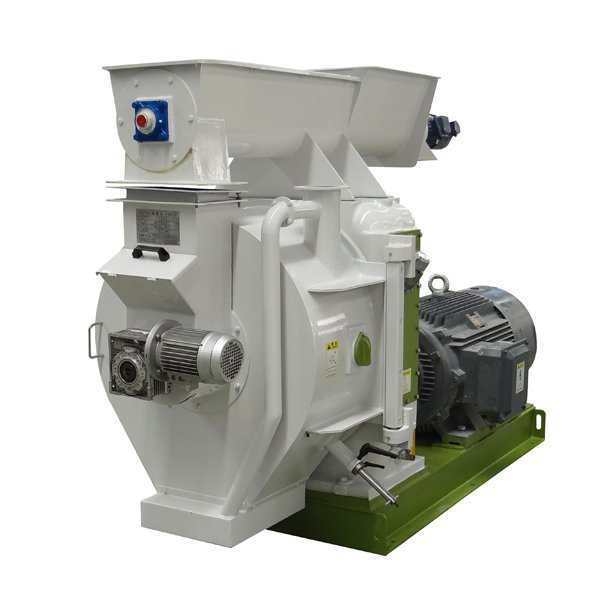
The die is a consumable and a tuning instrument at the same time. Its effective length-to-diameter ratio (L/D) sets compression. For softwood sawdust, an L/D around 1:6 to 1:10 is a common working band in our builds, with thicker dies used for hard, resinous or low-lignin materials that refuse to bind. Die thickness in our standard range runs from 35 to 100 mm on die diameters from 420 to 1,350 mm depending on model, with die speeds of 120–300 rpm selected per application. Compression ratio is also where new plants get into trouble: chasing high durability with an aggressive die on dry material produces blocked dies and burnt bearings, while a conservative die produces pellets that fail the tumbling test.
Energy-wise, the pellet mill is more moderate than buyers expect. The same IEA-cited chain lists 48.9 kWh per tonne at the pellet mill and 30 kWh per tonne for steam conditioning. Our vertical pellet mill line, which mounts the die vertically for gravity-assisted feeding, is specified in the range of 30–55 kWh per tonne of actual consumption. The pellet mill’s share of electricity is large because it runs continuously at high load — the IRENA reference plant allots it 56 of the plant’s 171 kWh/t of total electricity — but its share of total energy is modest next to thermal drying.
Stage 6: Cooling, Screening and Dust Control
Pellets leave the die at 70–90°C and too soft to handle. A counterflow cooler brings them to within a few degrees of ambient while the counter-current airflow cools the hottest pellets last, avoiding thermal shock cracking. Cooling is not optional quality polish: pellets conveyed and bagged hot will sweat in the bag, and the moisture that condenses on the bag wall softens the pellets at contact points, which is a classic cause of customer complaints about “melted” pellets.
After cooling, a screener separates fines and short pieces back to the inlet side, where they can be re-pelletized. Keeping the fines loop closed is what protects the ENplus fines limit at delivery; it also feeds the boiler with reject material that would otherwise be sold as sub-grade.
Dust collection deserves its own line item. Hammer milling and pelletizing generate fine dust continuously, and a pulse-jet filter sized for the actual air volumes — not a catalogue guess — protects both the operators and the motors. Dust is also a combustibility hazard, so filter placement and explosion venting should be reviewed with the supplier at layout stage, not after commissioning.
Stage 7: Bagging and Load-Out
The last stage depends entirely on the sales channel. Bulk export shipments use flat storage and loaders; domestic retail uses small bags (typically 15–20 kg) on a packing scale with a sewing or heat-sealing line; commercial buyers often want Big Bags at 500–1,200 kg filled on a ton-bag scale. A plant that plans to serve both retail and bulk should reserve floor space and conveyor routing for both from the start, because retrofitting a bagging line into a finished building is a disruption no operator enjoys.
Matching Capacities Across the Line
With the stages defined, the sizing question becomes concrete. The table below shows indicative configurations at four common plant sizes, drawn from our standard biomass product range. Treat the kilowatt figures as installed motor ratings on the pelletizing stage, not as energy consumption — rated power is sized for the worst case and actual draw per tonne lands lower, as the energy section below explains.
| Plant size | Pelletizing stage | Drying | Grinding | Typical layout note |
|---|---|---|---|---|
| 1–2 t/h | One vertical mill, 22–160 kW class, or compact ring die | Single-pass drum dryer | One hammer mill | Semi-auto bagging; suited to dry sawdust feed |
| 3–5 t/h | One ring die mill, 90–400 kW class with conditioner | Three-pass drum dryer | Primary hammer mill + fine grind | Buffer silo between dryer and mill; auto small-bag line |
| 5–10 t/h | One large ring die mill or two medium mills | Large three-pass dryer with dedicated biomass furnace | Two-stage grinding with inter-stage silo | Bulk + Big Bag load-out; full dust extraction system |
| 10+ t/h | Multiple parallel pelletizing lines | Dryer sized on evaporation duty, not t/h | Dedicated grinding hall | Redundancy per stage becomes affordable and wise |
Two sizing rules hide inside this table. The dryer is sized on evaporation duty — tonnes of water per hour — which depends on incoming moisture, so the same nominal 5 t/h plant needs a very different dryer for 55% wet chips than for 12% sawdust. And beyond roughly 10 t/h, single-machine solutions stop being wise: two medium pellet mills with an independent spare die set give more uptime than one very large mill, because a die change that idles half the plant idles only half.
Energy Per Tonne: What the Published Numbers Say
Energy is the cost category buyers most often underestimate, partly because thermal drying energy is usually self-generated biomass rather than a metered electricity bill, and partly because quoted motor powers are not consumption. The table below collects published stage-level figures for a conventional wood pellet chain, from wet feedstock to finished pellet, so you can sanity-check any supplier’s consumption claims.
| Stage | Specific energy (kWh/t output) | Source |
|---|---|---|
| Stage-1 grinder, 50.8 mm screen | 94.1 | Tumuluru (2016), IEA Task 40 annex |
| Rotary dryer, 30% → 10% moisture | 340.8 (thermal, ~65–70% of process energy) | Tumuluru (2016); Lamers et al. (2015) |
| Stage-2 grinder, 6.4 mm screen | 43.2 | Tumuluru (2016) |
| Steam conditioning | 30.0 | Tumuluru (2016) |
| Pellet mill | 48.9 | Tumuluru (2016) |
| Whole plant electricity (reference plant) | 171 (wood yard 20, pre-dryer 45, hammer mills 50, pellet mills 56) | IRENA (2019), citing Koppejan et al. (2012) |
Read these figures with their definitions attached. The IRENA total is electricity only; drying heat is reported separately, which is why the same publication lists the pellet mill as the largest single electrical consumer while the IEA chain shows drying as the dominant energy user overall. Rated motor power divided by rated output — the arithmetic behind many supplier claims — produces a ceiling, not a measurement, because motors are sized for worst-case starting and blockage loads. When you compare quotations, ask each supplier to state expected kWh per tonne of electricity at your actual moisture, and to separate thermal drying energy, including the fuel it expects the furnace to burn.
Five Design Mistakes That Show Up in the First Month
1. Sizing the dryer on the supplier’s test material. Dryer performance data produced on 12% sawdust says nothing about your 55% eucalyptus chips. Insist on an evaporation-duty calculation using your moisture analysis.
2. Skipping the buffer silos. Direct coupling of a hammer mill to a dryer to a pellet mill means every stage hiccup propagates instantly. Two well-placed buffer silos are the cheapest uptime insurance in the plant.
3. Buying durability from the die alone. A thicker die raises compression, but if particle size distribution and conditioning are wrong, the die only blocks faster. Durability is a chain property.
4. Undersizing dust extraction. Filters chosen on price rather than air volume load the motors, leak dust into the hall, and in the worst case turn the plant into a combustible-dust risk that an inspector will find.
5. Planning bagging last. Load-out determines labor staffing, shift patterns and the cooler’s discharge rhythm. A plant that must pause pelleting to change bag formats loses more capacity in a year than the bagging line costs.
What to Send a Supplier for an Accurate Quote
The difference between a generic quotation and a real engineering proposal is the quality of the input data. Before requesting pricing on a wood pellet production line, prepare:
Raw material analysis: species, form (logs, chips, sawdust), incoming moisture range across seasons, ash content, and annual volume available. Target pellet specification: ENplus grade or national equivalent, target diameter, and intended sales channel. Site data: hall dimensions and height, power supply capacity and tariff, water availability for steam, and whether a biomass furnace is acceptable. Commercial targets: expected annual operating hours, shift pattern, and the t/h figure you actually need after downtime, not nameplate. With these inputs, a supplier can commit to evaporation duty, die configuration and expected specific energy — the three numbers that separate a working line from an expensive demonstration.
Bottom Line
A wood pellet production line is a moisture-moving system with a pellet mill at the end of it. Fix the fuel specification first, size the dryer on evaporation duty from your own raw material data, protect the interfaces with buffer capacity, and demand stage-level energy figures in the same units from every supplier you compare. Plants designed this way reach their rated capacity in weeks instead of quarters, and the equipment choices — chipper class, grinder screens, die geometry, cooler type — become verifiable decisions instead of catalogue bets. If you want that comparison run against your raw material, send us your moisture analysis and target capacity and we will return a stage-by-stage configuration with the energy arithmetic attached.