
Pellets do not leave the pellet mill finished. They leave it hot, moist and soft — and everything that happens in the ten to twenty minutes afterward decides whether they arrive at the customer as sellable product or as a bag of fines. The counterflow cooler is the machine that handles that step, and understanding its working principle is the fastest way to diagnose most post-pelleting quality complaints. This article walks through the physics, the operating variables and the failure modes, with the numbers attributed to their sources.
What Leaves the Die Is Not a Finished Pellet
Conditioning and compression heat the mash well past what storage allows. FAO’s feed milling reference (FAO, Chapter 18, Feed Milling Processes) describes steam conditioning as adding moisture as steam to soften particles and gelatinize starch before the die — in practice, mash moves from roughly 10–12% moisture at ambient temperature to 15–16% moisture at 80–90°C before compression. Die friction adds more heat on the way through.
The pellets that drop out of the die therefore sit at roughly 70–90°C with moisture above the storage-safe level, mechanically soft enough to deform under a conveyor or bagger. Bag them hot and three things go wrong, in order: surface moisture condenses inside the bag, mold follows within days, and the whole batch is lost. Industry summaries put the required finish at within 3–5°C of ambient temperature and around 11.5–13.5% moisture for most feeds, with FAO’s hazard-analysis example for maize-based feed setting a critical limit of 13% moisture just before packaging. Cooling is what closes that gap — removing roughly 3–5 percentage points of moisture while pulling the temperature down.
The Counterflow Principle
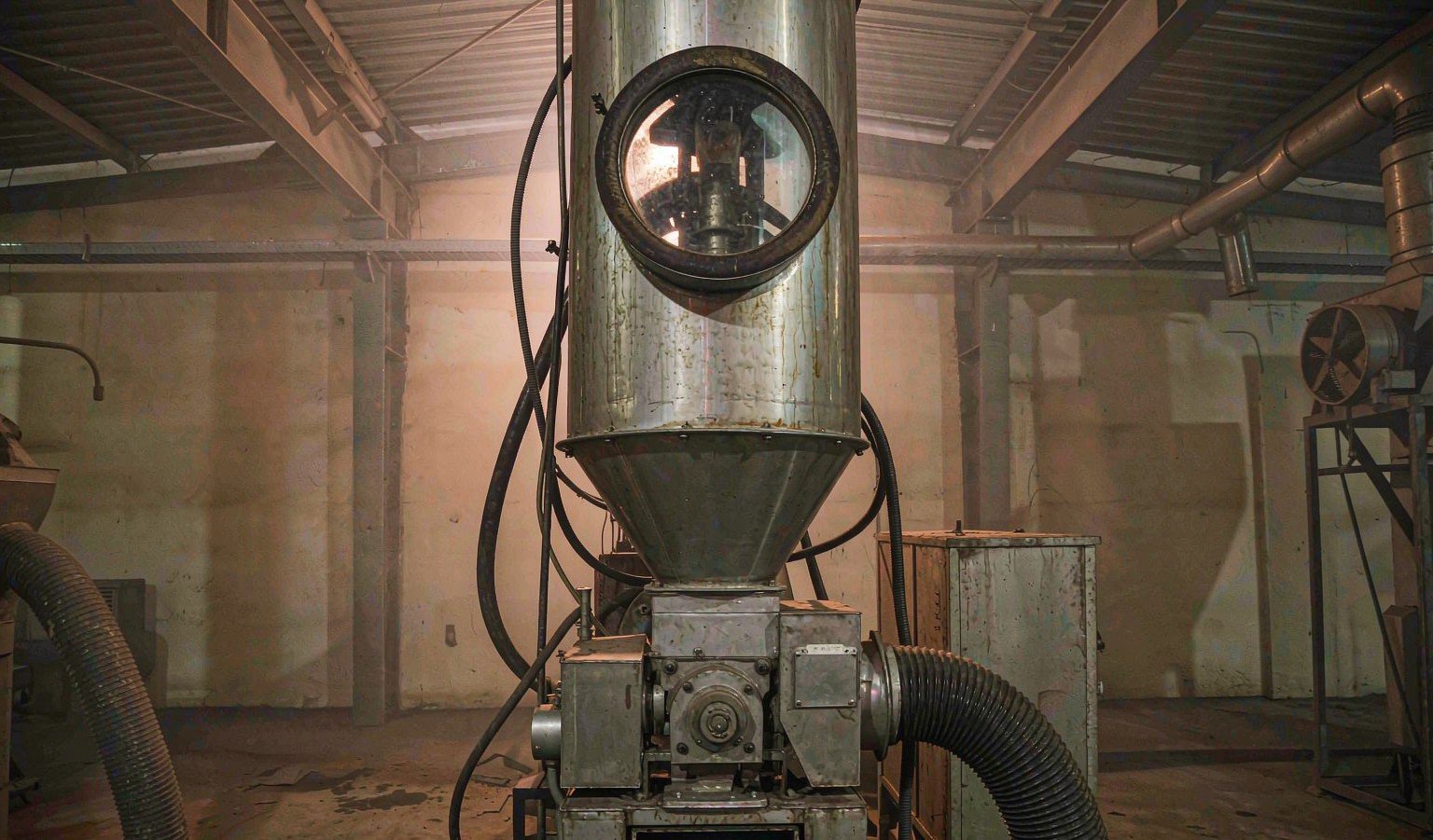
A counterflow cooler is a vertical column holding a deep, slowly descending bed of pellets. Ambient air is drawn upward through the bed by a suction fan; pellets move downward by gravity. The two streams travel in opposite directions — hence the name.
The direction is not a design flourish. It arranges the temperature gradients so that:
- The coldest air meets the coldest pellets. Fresh ambient air enters at the bottom, where pellets have nearly finished cooling. No pellet ever meets an air blast much colder than itself, so the pellet surface and core cool at nearly the same rate — no thermal shock, no surface case-hardening that traps moisture inside, no check-cracking.
- The hottest air leaves at the top. Exhaust air exits near the inlet, where incoming pellets are hottest, so the air leaves carrying as much heat and moisture as possible. The result is a smaller fan doing less work for the same cooling duty than co-current or cross-flow designs.
This staged, gentle cooling matters because the pellet is still solidifying. Starch retrogradation and protein setting continue as the pellet cools; cool the outside much faster than the inside and you build internal stress that later shows up as fines at the sifter. As one biomass-industry explainer (Kingwood, counterflow cooling in pellet lines) puts it, the bed maximizes the temperature gradient across its depth, which is exactly what a fragile, still-hot pellet needs.
Zone by Zone Through the Column

Follow a pellet down the column and the machine divides itself into four functional zones:
- Inlet and distribution. Hot pellets enter through an airlock rotary valve at the top, which lets material in while keeping the exhaust air from escaping. A distributing mechanism spreads pellets into an even bed — uneven beds channel the airflow and leave wet pockets.
- Top of the bed: pre-cooling. Incoming pellets meet air that has already passed through the whole column — warm and nearly saturated, but still cooler and drier than the pellets. Initial surface heat comes off without shocking the pellet.
- Middle of the bed: the work zone. Most of the moisture transfer happens here, as steady evaporation pulls both heat and the conditioning water out of the pellet core. This is where residence time earns its keep.
- Bottom: final cooling and discharge. Pellets meet fresh ambient air for the last few degrees, then pass through the discharge mechanism — a rotary grate or slide valve whose speed is the machine’s primary control, because discharge rate sets bed depth and bed depth sets residence time. An airlock below keeps the suction sealed.
Behind the column sit the fan, a cyclone (or the workshop dust collection system) to strip out aspirated fines, and ducting. The fan is not an accessory — it is half the machine, and undersizing it is the most common way a cooler ends up undersized overall.
The Four Operating Variables
| Variable | Typical range | Effect of getting it wrong |
|---|---|---|
| Residence time (bed depth × discharge speed) | 6–10 min for most livestock feed pellets; 15–25 min for dense biomass pellets (industry practice) | Too short: hot, moist core → sweating and caking in the bag. Too long: over-dried, brittle pellets and lost capacity |
| Airflow | Roughly 1.0–1.5 m³ air per kg of pellets; air speed through the bed about 0.8–1.5 m/s (vendor guidance, e.g. Victor) | Too little: under-cooling in humid weather. Too much: surface over-drying, cracked pellets, wasted fan power |
| Inlet air condition | Ambient; capacity drops in hot, humid weather | High-humidity air dries less per pass — tropical plants need margin in the fan, not nameplate luck |
| Bed evenness | Level, evenly distributed bed | Channeling: some pellets get double airflow, others barely any — the origin of “some bags fine, some bags moldy” complaints |
Ranges compiled from published vendor and industry sources cited in the text; verify against your own pellet diameter, density and climate.
Cooling Targets and How to Verify Them
| Parameter | Target | How to check |
|---|---|---|
| Discharge temperature | Ambient +3–5°C | Handheld IR gun on the discharge stream each shift |
| Discharge moisture | 11.5–13.5% for most feeds; ≤13% critical limit in FAO’s packaging example | Calibrated moisture meter at cooler discharge, before bagging |
| Fines after cooler/sifter | ≤1–2% preferred | Sifter tailings check; trend it — a rising trend often points at cooling |
| Bed behavior | Even descent, no stagnant corners | Inspection window; check after every recipe change |
Counterflow vs Pendulum Cooling

Counterflow is the default for feed and biomass pellets because it is compact, enclosed and efficient. It is not the only design. A pendulum cooler moves product in thin agitated layers rather than a deep static bed: cooling is faster per unit volume and handling is gentler, which suits fragile expanded or high-fat pellets, at the cost of more moving product contact and higher aspiration load. For standard 3–8 mm feed and biomass pellets, a deep-bed counterflow cooler remains the specification we recommend most often — but the choice should be made on product fragility and line layout, not habit.
Failure Modes and What They Cost
- Condensation on cold metal. Warm humid exhaust air condenses on cooler housings and downstream bins, then drips back or molds. Keep exhaust ducts short and insulated where needed, and never throttle the fan below design airflow to “save power.”
- Over-drying. Excess airflow or excessive residence makes the pellet surface brittle; the sifter shows it first. Dial back fan speed (a VFD pays for itself here) or speed up discharge.
- Undersized cooler. If the cooler lags the pellet mill by more than roughly 15% of throughput, hot pellets accumulate at the inlet and the effective residence time collapses — warm, soft pellets reach the bagger and rejection rates climb. Size the cooler for the mill’s real peak, not its average.
- Uneven distribution. After every die change or capacity step, watch the bed through the inspection window. Re-distribute before blaming the fan.
Cooling also interacts with everything upstream. If pellets arrive at the cooler with unstable moisture — usually a conditioning problem — no cooler setting will fully rescue them; our steam conditioning analysis covers that half of the moisture balance, and our 5 t/h poultry feed mill walkthrough shows where cooling sits in a complete line layout.
Next Steps
If you are specifying cooling for a new line, work through this order: fix the finished-moisture target for your product and market; size the cooler for the pellet mill’s peak output at your worst-case humidity, not your average day; pair it with a cyclone and dust collection sized for the same airflow; and put discharge temperature and moisture checks into the shift routine from day one. For existing lines, the cheapest audit is a thermometer and a moisture meter at the cooler discharge for one week — the data will tell you whether the problem is residence time, airflow or something upstream.
To review cooling and screening options matched to your line capacity, see our cooler and screener range, or the rotary screener that normally follows the cooler. Send us your pellet diameter, line capacity and climate data, and we will return a cooling specification with the airflow and residence-time assumptions shown.