

A dust collector that is “close enough” in size is one of the most expensive compromises in a feed mill or pellet plant. The unit still runs, the fan still turns, but the pressure drop climbs, the cleaning system fires constantly, bags or cartridges age twice as fast, and the mill operator responds by throttling dampers — which pushes dust back into the workshop. Sizing a pulse jet collector is not black magic; it is a short sequence of arithmetic with published starting values. This article walks through that sequence for feed and biomass dust, with a worked example for a 5 t/h feed line.
Step 1: Map the Capture Points and Their Airflows
List every point where dust becomes airborne: hammer mill inlet and outlet, mixer discharge, pellet mill conditioning and pressing zone, cooler discharge and cyclone tail, transfer points between bucket elevators and conveyors, and the bagging station. For each point, the hood or enclosure must pull enough air to keep dust inside the capture zone. As a design exercise for the worked example below, we assume a 5 t/h feed line with five capture points — hammer mill 2,000 cfm, mixer 1,000, pellet mill 1,200, cooler 1,500, bagging 500. These are design assumptions for illustration; your actual numbers come from the equipment supplier’s aspiration requirements and hood design. What matters is that the list is complete, because the collector sees the sum, and the one point you forgot is the one that will leak dust.
Step 2: Add the Airflows and Apply a Deliberate Margin
Total design airflow for the example is 6,200 cfm (about 10,540 m³/h). Practical systems add a margin for damper imbalance, filter ageing and minor leakage — 10 to 15% is common practice. Sizing at 6,800–7,100 cfm keeps the fan operating point sane as the system ages. Do not confuse this margin with the air-to-cloth ratio, which is a separate decision in the next step.
Step 3: Choose the Air-to-Cloth Ratio From Published Values
The air-to-cloth (A/C) ratio — actual cubic feet per minute of air divided by net square feet of filter media — is the number that determines the physical size of the collector. The most widely used published starting values are in Table 1.1 of the baghouse chapter of the EPA Air Pollution Control Cost Manual, which lists “generally safe design values” by dust type and cleaning method. The rows that matter for feed and biomass plants look like this:
| Dust | Shaker / reverse-air, woven | Pulse jet, felt |
|---|---|---|
| Feeds, grain | 3.5 | 14 |
| Sawdust (wood) | 3.5 | 12 |
| Flour | 3.0 | 12 |
| Starch | 3.0 | 8 |
| Sugar | 2.0 | 13 |
The EPA is explicit that these are starting points: particle size distribution and grain loading both push the final choice down from the table value. Fine, uniformly sized particles form dense filter cakes; sticky or oily particles do the same regardless of size. A mixed feed mill stream — flour-like dust from grinding plus coarser fibrous dust from the cooler line — is a good candidate to use the more conservative row (12 ft/min) rather than the most aggressive one.
Our own collector ranges reflect the same logic: the round pulse filter series is rated at 500–10,000 CFM with air-to-cloth ratios of 2:1 to 5:1 depending on dust characteristics, and the square pulse filter series runs 3:1 to 6:1. Those bands are more conservative than the EPA table maximums because cartridge media, shorter cleaning pulses and continuous duty on abrasive dust all justify staying low.

Step 4: Convert Airflow to Filter Area
Divide design airflow by the chosen A/C ratio. For the example, 6,800 cfm ÷ 12 ft/min = about 570 ft² of net cloth area. If the collector is a compartmented baghouse cleaned off-line, EPA’s Table 1.2 gives multipliers to convert net to gross area (roughly ×2 below 4,000 ft², ×1.5 for 4,000–12,000 ft², tapering to ×1.04 above 180,000 ft²) so that the net area is preserved while one compartment is isolated for cleaning. Cartridge units cleaned on-line, like the round pulse filter above, do not take that multiplier — the quoted cartridge count and media area is what you get. For the example, a unit in the 8,000–10,000 CFM class with 12–16 cartridges clears the 570 ft² requirement with the margin intact.
Step 5: Check Pressure Drop and Fan Power
EPA’s baghouse chapter puts typical system pressure drop at 5 to 20 inches of water column; well-run pulse jet installations on grain dust sit toward the lower half of that band, with our square pulse filter series specifying an operating differential of −10 to −25 inches depending on configuration. Assume 8 inches for the worked example. Fan shaft power follows:
P (kW) = Q (m³/s) × Δp (Pa) ÷ (1000 × fan efficiency)
For 6,800 cfm (3.21 m³/s) at 8 in. w.c. (1,993 Pa) and 60% combined efficiency, the fan draws about 10.7 kW — call it an 11 kW motor. The instructive part is the sensitivity: a collector sized at 16 ft/min instead of 12 runs higher pressure drop and constant cleaning, and the fan power, compressed-air consumption and media replacement cost all climb together. Undersizing does not save money; it moves the cost into the operating budget where nobody reviews it. The EPA’s pulse jet fabric filter fact sheet notes that new pulse jet equipment achieves collection efficiencies of 99–99.9% — but that efficiency holds only at the designed velocity, not at whatever velocity your throttled-back system ends up running.
Step 6: Keep Duct Velocities Above Transport Minimums
A correctly sized collector with undersized ductwork still plugs up. Branch and main duct velocities must stay above the minimum transport velocity for the dust: standard industrial ventilation practice (ACGIH Industrial Ventilation manual values) puts grain dust at roughly 3,500–4,500 fpm, with wood dust in a similar band. Below that, dust settles in the duct, and the settled cake is both a fire load and a flow restriction that changes the fan’s operating point. When we lay out a dust system for a customer, duct sizing is checked against the collector, not sized independently — the two are one hydraulic system.
Step 7: Deal With Combustible Dust Compliance Early
Grain dust, flour and fine wood dust are combustible. In the US, OSHA’s Grain Handling Facilities standard (29 CFR 1910.272) sets housekeeping and dust accumulation limits inside grain handling areas, and NFPA’s NFPA 652 requires a dust hazard analysis (DHA) for facilities handling combustible dusts, with NFPA 61 covering agricultural and food processing specifics. For the collector itself this typically means explosion venting or suppression sized to the hazard, grounding to prevent static ignition, isolation devices between the collector and the process, and no horizontal ledges inside the housing where dust can settle. Retrofitting a vent panel after the housing is built costs several times what specifying it does — so this belongs in step 7 of sizing, not in the punch list after commissioning.
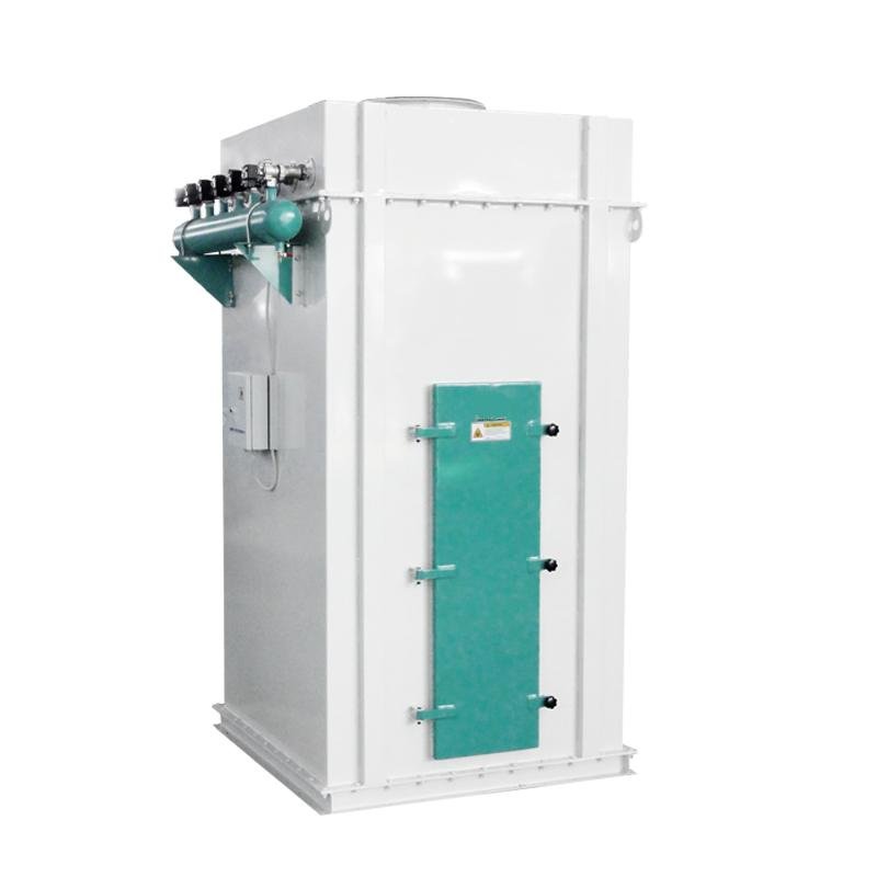
Worked Example: 5 t/h Feed Line, All Steps Together
| Step | Result |
|---|---|
| Capture points | Hammer mill 2,000 / mixer 1,000 / pellet mill 1,200 / cooler 1,500 / bagging 500 cfm |
| Design airflow (+10–15% margin) | 6,800 cfm (≈11,500 m³/h) |
| A/C ratio (EPA, mixed feed/wood dust, pulse jet felt) | 12 ft/min (conservative row) |
| Required net cloth area | ≈570 ft² |
| Selected unit class | Round pulse filter, 8,000–10,000 CFM class, 12–16 cartridges |
| Assumed system Δp / fan power | 8 in. w.c. → ~11 kW fan motor |
| Compliance items specified with the housing | Explosion venting per DHA, isolation valve, grounding, rotary airlock discharge |
On that last row: the discharge under a collector is itself a dust-tight interface. A leaking discharge re-entrains everything the unit just caught, which is why the collector and the rotary airlock underneath it are specified as a pair.
Four Sizing Mistakes That Show Up Within a Year
- Sizing to nameplate airflow instead of hood airflow. Equipment brochures state aspiration requirements; hoods and duct losses determine what the fan actually delivers. Measure or calculate the system, then size.
- Using one A/C ratio for every dust. The EPA table’s spread between starch (8 ft/min) and feeds/grain (14 ft/min) is not noise — it reflects how differently these cakes form. A mixed stream gets the conservative value.
- Forgetting the off-line cleaning multiplier. A compartmented unit that cleans off-line needs gross area well above the net requirement, or capacity drops every time a compartment isolates.
- Treating compliance as an accessory. Vent panels, isolation and grounding specified after fabrication cost more and often fit worse. The DHA should be finished before the collector drawing is approved.
Peer-written sizing articles from other equipment makers can be a useful second opinion once you have your own numbers — this air-to-cloth calculation walkthrough covers the same arithmetic from a supplier’s perspective, including a case where duct leakage pushed the real A/C ratio far above the design value.
Next Steps
- Walk the plant with a camera and list every capture point — including transfer points that were “temporary” three years ago and never got aspiration.
- Collect each machine supplier’s stated aspiration airflow, and flag any point where the hood was designed in-house.
- Fix the dust type per stream (feeds/grain vs. sawdust vs. starch-heavy), then pick the A/C row from the EPA table — conservative side for mixed streams.
- Do the net-to-gross arithmetic and the fan power calculation before requesting quotes, so supplier proposals can be compared like for like.
- Start the DHA conversation early if you handle grain dust or fine wood dust; it changes the housing, not just the paperwork.
If you send us the capture point list with airflows and the dust types, we will return a collector selection with filter area, cleaning configuration and fan duty for review — our product engineering team designs the pulse and cleaning equipment range as part of complete feed and pellet lines, so the collector, ducting and airlock arrive as one matched system rather than three separate purchases. For context on how dust and aspiration fit into a full plant layout, see our article on setting up a 5 t/h poultry feed mill.